Dell’s commitment to network efficiency and security has ushered in an innovative feature in its MX configuration – Ethernet with No Spanning Tree. This post delves into the significance of this updated feature, how it compares with the legacy Ethernet and the guidelines for deploying it effectively.
Introduction to Ethernet – No Spanning Tree
Dell introduced the Ethernet – No Spanning Tree feature starting with OME-M 1.20.00 and OS10.5.0.7 versions. This feature allows Ethernet uplinks to function as end hosts with multiple adapters connected to the upstream network, all while disabling the Spanning Tree Protocol (STP) on the uplink interfaces.
Comparing Legacy Ethernet with Ethernet – No Spanning Tree
Legacy Ethernet:
Legacy Ethernet in Dell MX Chassis traditionally uses standard networking protocols, including the Spanning Tree Protocol (STP). STP is known to prevent network loops by blocking redundant paths. However, this can lead to latency due to reconvergence times during network changes and inefficient bandwidth usage since some links are blocked.
Ethernet – No Spanning Tree:
In contrast, Ethernet – No Spanning Tree doesn’t utilize STP. Instead, it employs technologies such as Multi-Chassis Link Aggregation (MLAG) or Shortest Path Bridging (SPB) to avoid loops and efficiently use network paths. This method supports multiple active paths, reducing convergence times and optimizing bandwidth usage.
Why Ethernet – No Spanning Tree is the Preferred Option
Efficient Bandwidth Utilization: MLAG allows for the simultaneous utilization of multiple paths instead of STP, which blocks redundant paths.
Faster Convergence: It enables the network to adapt more quickly to changes, which is vital in modern data centers where low latency is essential.
Simpler Configuration and Management: Managing networks without STP is often simpler and void of the complexities associated with STP configurations.
Scalability: Ethernet – No Spanning Tree can efficiently handle a large number of active paths, which is particularly advantageous in extensive and expanding networks.
Working Mechanism and Advantages
The Ethernet – No Spanning Tree uplink type maintains a loop-free topology without relying on STP by preventing VLANs from overlapping across uplinks. This versatile feature supports several use cases, as highlighted in Dell’s guide. The key advantages of using Ethernet – No Spanning Tree in Dell MX configurations include the following:
Prevention of Network Loops: It ensures that VLAN IDs do not overlap across uplinks, thus avoiding network loops more robustly and reliably than STP.
Improved Network Efficiency: Disabling STP and maintaining a loop-free topology facilitates more efficient data pathways, reducing unnecessary network traffic and enhancing overall performance.
Increased Flexibility and Interoperability: It supports connections to Dell and non-Dell switches in a vPC/VLT configuration, offering more flexibility in diverse network environments.
Support for Advanced Interfaces: Compatible with modern network standards like QSFP28 and QSFP28-DD on the MX9116n FSE with OME-M 1.20.00 and later versions.
Simplified Network Management: Representing a SmartFabric as an end host with multiple adapters to the upstream network simplifies network management and topology design.
Guidelines for Deployment
While deploying the Ethernet – No Spanning Tree feature, keep the following guidelines in mind:
1. Before creating Ethernet – No Spanning Tree uplinks, remove Legacy Ethernet uplinks from an existing SmartFabric to avoid network loops.
2. Ethernet – No Spanning Tree uplinks cannot coexist with Legacy Ethernet uplinks in the same SmartFabric.
3. VLAN IDs, both tagged or untagged, must not overlap to maintain network efficiency and prevent conflicts.
4. FCoE Uplinks require separate untagged VLAN IDs to ensure smooth operation.
5. Initially, only QSFP28 interfaces on the MX9116n FSE were supported for Ethernet – No Spanning Tree uplinks, but with OME-M 1.20.10 and later versions, QSFP28-DD interfaces are also supported.
Conclusion
Ethernet – No Spanning Tree in Dell MX configuration offers a progressive approach to networking. Its capability to enhance network efficiency and reliability is a significant upgrade from the traditional Legacy Ethernet. Adherence to the deployment guidelines ensures that organizations can leverage the full potential of this innovative feature in their Dell MX ecosystem.
Cisco Configuration
Note:
I’m assuming your VPC Domain is already set up. Also, do not use VLAN 1 for Untagged traffic. It’s recommended you change this default.
Set up the necessary VLANs on each switch. In this particular deployment, VLAN 10 is utilized as the Tagged VLAN, while VLAN 111 is employed for Untagged traffic. Deactivate the spanning tree protocol on these VLANs.
Leaf A:
interface vlan111
  description "Default VLAN"
  no spanning-tree mode
  no shutdown

interface vlan10
  description "General Purpose"
  no spanning-tree mode
  no shutdown

Leaf B:
interface vlan111
description "Default VLAN"
no spanning-tree mode
no shutdown

interface vlan10
  description "General Purpose"
  no spanning-tree mode
  no shutdown
Execute the subsequent commands to establish port channels that will link to the downstream MX9116n FSEs. Once the configuration is complete, exit the configuration mode and preserve the settings. For the port channel that is connected to the MX9116n FSE, ensure that the spanning tree protocol is disabled.
Leaf A:
interface port-channel1
  description To MX Chassis
  switchport
  switchport mode trunk
  switchport trunk allowed vlan 10,111
  spanning-tree bpduguard enable
  spanning-tree port type edge
  spanning-tree guard root
  vpc 222

interface Ethernet1/1
description To MX Chassis 1
switchport
switchport mode trunk
switchport trunk allowed vlan 10,111
channel-group 1 mode active
no shutdown

interface Ethernet1/2
description To MX Chassis 2
switchport
switchport mode trunk
switchport trunk allowed vlan 10,111
channel-group 1 mode active
no shutdown
end

copy running-configuration startupconfiguration

Leaf B:
interface port-channel1
description To MX Chassis
switchport
switchport mode trunk
switchport trunk allowed vlan 10,111
spanning-tree bpduguard enable
spanning-tree port type edge
spanning-tree guard root
vpc 222

interface Ethernet1/1
description To MX Chassis 1
switchport
switchport mode trunk
switchport trunk allowed vlan 10,111
channel-group 1 mode active
no shutdown

interface Ethernet1/2
description To MX Chassis 2
switchport
switchport mode trunk
switchport trunk allowed vlan 10,111
channel-group 1 mode active
no shutdown
end

copy running-configuration startupconfiguration
Explaining the Cisco Configuration
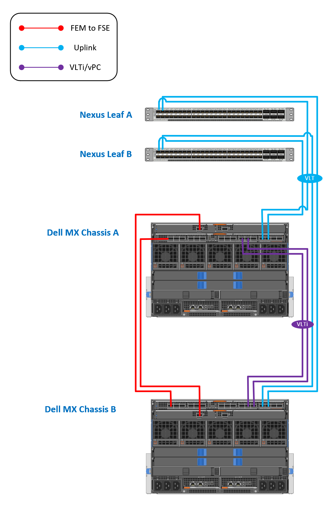
This configuration demonstrates how to set up VLANs and port channels on two Cisco Nexus switches (Leaf A and Leaf B) that are assumed to be part of a vPC (Virtual Port Channel) domain, and how to connect them to Dell MX9116n FSEs. Let’s break down the configuration step by step:
Configuring VLANs
For both switches, Leaf A and Leaf B, two VLANs are created: VLAN 111 and VLAN 10.
1. `interface vlan111` and `interface vlan10`: Entering interface configuration mode for the specific VLANs (111 and 10).
2. `description “Default VLAN”` and `description “General Purpose”`: Assigning a description to the VLAN interfaces for documentation purposes.
3. `no spanning-tree mode`: Disabling Spanning Tree Protocol on these VLANs. This is usually done in specific scenarios where STP is not desired.
4. `no shutdown`: Ensuring that the VLAN interfaces are active.
Configuring Port Channels
Port channels are used to aggregate multiple physical interfaces into a single logical interface. In this configuration, the port channels are used to connect to the downstream MX9116n FSEs.
1. `interface port-channel1`: Entering interface configuration mode for the port-channel.
2. `description To MX Chassis`: Assigning a description to the port-channel for documentation purposes.
3. `switchport`: Configuring the interface as a Layer 2 switchport.
4. `switchport mode trunk`: Setting the link type to “trunk,” which means it can carry traffic for multiple VLANs.
5. `switchport trunk allowed vlan 111,10`: Defining which VLANs are allowed to send traffic through the trunk. In this case, VLANs 111 and 10. This is where the configuration is different from the previous one.
6. `spanning-tree bpduguard enable`: Enabling BPDU Guard, which shuts down the port if it receives BPDU packets, preventing potential loops.
7. `spanning-tree port type edge`: Configuring the port as an edge port, assuming it’s connected to an end host and not another switch, which can expedite the transition through Spanning Tree states.
8. `spanning-tree guard root`: Preventing the port from becoming a root port in the Spanning Tree topology.
9. `vpc 222`: Associating the port-channel with a Virtual Port Channel (vPC). The number “222” is the vPC ID.
Configuring Physical Interfaces
Two physical Ethernet interfaces (Ethernet1/1 and Ethernet1/3) are added to the port-channel for both Leaf A and Leaf B.
1. `interface Ethernet1/1` and `interface Ethernet1/3`: Entering interface configuration mode for the specific Ethernet interfaces.
2. `description To MX Chassis 1` and `description To MX Chassis 2`: Assigning a description to the interfaces for documentation purposes.
3. `switchport`: Configuring the interface as a Layer 2 switchport.
4. `switchport mode trunk`: Setting the link type to “trunk”.
5. `switchport trunk allowed vlan 111,10`: Defining which VLANs are allowed to send traffic through the trunk. This matches the allowed VLANs on the port-channel.
6. `channel-group 1 mode active`: Adding the interface to port-channel 1 and configuring it to actively negotiate forming a port-channel using LACP (Link Aggregation Control Protocol).
7. `no shutdown`: Ensuring that the Ethernet interfaces are active.
Saving the Configuration
Finally, the configuration is saved to the startup configuration, which means it will persist across reboots.
8. `copy running-configuration startup-configuration`: Saving the running configuration to the startup configuration.
This configuration ensures a streamlined and robust connection between the switches and the downstream MX9116n FSEs. By meticulously setting up the VLANs and configuring the port channels with the proper parameters, network redundancy and efficient bandwidth utilization are achieved.
This configuration is essential in environments where high availability and performance are critical. The aggregation of physical links into a port-channel allows for higher bandwidth, load balancing, and provides a fault-tolerant connection.
It’s important to note that disabling the Spanning Tree Protocol in this context should be approached cautiously and a conscious decision based on the network topology and design considerations. Disabling STP removes the loop prevention mechanism, so make sure that the network is designed in a way that loops are not created.
Additionally, using descriptive labels for interfaces and VLANs aids in network documentation, which is invaluable for troubleshooting and understanding the purpose and function of different elements in the network.
In summary, this configuration is tailored for a specific scenario where VLAN 111 and VLAN 10 are required to be transmitted over trunk links, and it optimally configures the port-channels for high availability and performance in connection with MX9116n FSEs. This is essential in ensuring a resilient and high-performing network infrastructure. Proper documentation and understanding of the configuration are vital for network stability and ease of management.
Verify Spanning Tree
To verify the “No Spanning-Tree” or the “Spanning-Tree” mode from the Cisco switch side, you can use specific Cisco IOS command-line interface (CLI) commands.
For Spanning-Tree:
Dell:
Dell-MX> show interfaces switchport

Name: Ethernet1/1
Switchport: Enabled
Administrative Mode: trunk
Operational Mode: trunk
Administrative Trunking Encapsulation: dot1q
Negotiation of Trunking: On
Access Mode VLAN: 1 (default)
Trunking Native Mode VLAN: 1 (default)
Administrative Native VLAN tagging: enabled
...
Storm Control Broadcast: disabled
Storm Control Multicast: disabled
Storm Control Unicast: disabled
Storm Control Action: shutdown
Spanning-Tree: enabled
Cisco:
The command `show spanning-tree` will display the status of all interfaces. You would expect to see the interfaces connected to the Dell switch listed here if Spanning-Tree is in use.
Output should display the status of all ports. You can look at the ports connected to the Dell switch. If the protocol is enabled, the output for those ports should indicate they are in either a forwarding or blocking state.
Switch#show spanning-tree

VLAN0001
  Spanning tree enabled protocol ieee
  Root ID    Priority    32769
             Address     0016.c7a7.56d0
             This bridge is the root
             Hello Time  2 sec  Max Age 20 sec  Forward Delay 15 sec

  Bridge ID  Priority    32769  (priority 32768 sys-id-ext 1)
             Address     0016.c7a7.56d0
             Hello Time  2 sec  Max Age 20 sec  Forward Delay 15 sec
             Aging Time  20

Interface           Role Sts Cost      Prio.Nbr Type
------------------- ---- --- --------- -------- --------------------------------
Gi0/1               Desg FWD 4         128.1    P2p
Gi0/2               Desg FWD 4         128.2    P2p
For No Spanning-Tree:
Dell:
Dell-MX> show interfaces switchport

Name: Ethernet1/1
Switchport: Enabled
Administrative Mode: trunk
Operational Mode: trunk
Administrative Trunking Encapsulation: dot1q
Negotiation of Trunking: On
Access Mode VLAN: 1 (default)
Trunking Native Mode VLAN: 1 (default)
Administrative Native VLAN tagging: enabled
...
Storm Control Broadcast: disabled
Storm Control Multicast: disabled
Storm Control Unicast: disabled
Storm Control Action: shutdown
Spanning-Tree: disabled
Cisco:
If the No Spanning-Tree mode is enabled, you will not see the Dell switch interfaces in the Spanning-Tree output. Also, the command `show spanning-tree interface [interface-id]` should return a message indicating that Spanning Tree is not enabled on that port.
It’s also possible to check the configuration of the individual ports with the command `show running-config interface [interface-id]`. If you’re using No Spanning-Tree, you might see a command like `spanning-tree bpdufilter enable` on the specific port. This essentially disables Spanning-Tree on that interface by ignoring incoming BPDUs and not sending any BPDUs.
It’s worth noting that different Cisco switches and IOS versions may have different commands and outputs, so it’s always good to check the official Cisco documentation or contact Cisco support for the most accurate information.
Switch#show spanning-tree interface Gi0/1

% Spanning tree instance(s) do not exist for Gi0/1
Lastly, please remember to handle these configurations carefully, as incorrect settings could lead to network loops and disruptions. Always ensure you clearly understand the potential impacts before making changes to your network configuration.
Transceivers
Here are the fiber transceiver options for 100GbE connectivity between the Cisco Nexus and Dell MX chassis:
For the Cisco Nexus 9300:
Cisco QSFP-100G-SR4-S – Supports multimode fiber up to 100m
Cisco QSFP-100G-LR4-S – Supports single-mode fiber up to 10km
Cisco QSFP-100G-CWDM4-S – Supports single-mode fiber up to 2km
For the Dell MX chassis:
Dell Q28-100G-SR4 – Multimode fiber up to 100m
Dell Q28-100G-LR4 – Single-mode fiber up to 10km
Dell Q28-100G-CWDM4 – Single-mode fiber up to 2km
The compatible options are:
Multimode – Cisco QSFP-100G-SR4-S and Dell Q28-100G-SR4
Single-mode 10km – Cisco QSFP-100G-LR4-S and Dell Q28-100G-LR4
Single-mode 2km – Cisco QSFP-100G-CWDM4-S and Dell Q28-100G-CWDM4
So in summary, you can use either multimode or single-mode fiber transceivers to get 100GbE connectivity between the Cisco Nexus 9300 and Dell MX platforms over varying distances.